Compute Module Carrier Board

Celerity’s COM carrier board is an evaluation platform for Celerity’s Compute Module boards. The Compute Module carrier board brings out multiple interfaces from the COM connector, giving the user greater ease in testing and evaluating the peripherals available on the Compute Modules. The carrier board is powered by a single external 12V power supply. It provides devices on core interface busses in order for system evaluation and testing. More Compute Module specific interfaces are brought out to two auxiliary connectors, allowing evaluation of multiple Compute Modules on a single evaluation platform.
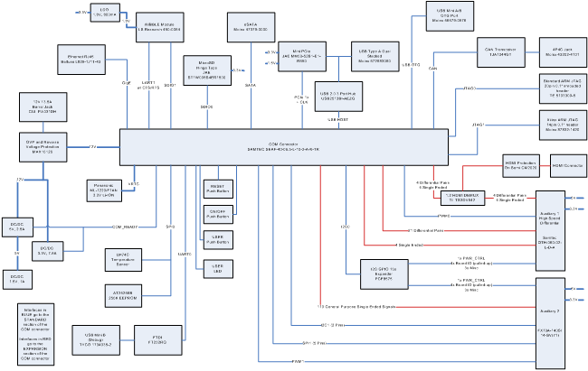
The standard interfaces and devices available for access on the carrier board include:
- 1x HMDI display connector
- 1x eSATA connector
- 1x MicroSD card slot
- 1x PCIe Mini Slot
- 1x USB OTG
- 2x USB 2.0 Host
- 1x Gigabit Ethernet jack with magnetics
- 1x WLAN/BLE via LS Research TiWi/BLE Module
- 1x USB/UART debug port
- 1x 20-Pin ARM JTAG
- 1x 14-Pin Xilinx JTAG
- 1x CAN port
- 1x SPI based EEPROM
- 1x SPI based Temperature Sensor
- 1x I2C GPIO Expander
In addition, two auxiliary connectors are provided to bring out any extra functionality provided by a specific COM module. The AUX0 connector is a high speed connector that allows high speed differential pair signals on the COM module to be brought out to a daughter board. The AUX1 connector brings out the remaining pads available on the COM module and allows multiple daughter boards to be connected.
Below is the block diagram of the carrier card.